
Abstract:For terminal users of Raise Boring Machines (RBM), the correct mounting and maintenance of cutter saddles (often referred to as the seat of the cutter) are critical to operational safety, equipment longevity, and boring efficiency. This comprehensive guide provides step-by-step technical instructions on mounting saddles on reaming heads, including critical torque specifications, the role of dowel pins, hardware lifecycle rules, and specialized saddle applications like the 7008-2013 inner saddle. By adhering to these manufacturer-aligned best practices, operators can prevent premature cutter failure, ensure optimal rock spalling, and minimize costly downtime during raise boring operations.
Core Keywords:Raise Boring Machine saddles, Seat of Cutter, RBM reaming head mounting, Cutter saddle torque specifications, Nord-lock washers, 7008-2013 inner saddle, D-type reaming heads, Raise boring equipment maintenance, Gauge saddle system.
In the demanding environment of raise boring, the reaming head is subjected to extreme rotational forces, immense thrust, and severe vibration. At the heart of this mechanical ecosystem is the saddle—or the seat of the cutter. The saddle is the critical interface between the heavy-duty roller cutters and the reaming head frame. Its primary function is to hold the cutter securely at a highly specific angle and distance from the center, ensuring a consistent Cutting profile and efficient rock spalling.
A poorly mounted or improperly selected saddle can lead to catastrophic equipment failure, irregular boreholes, and excessive wear on the cutters. This guide is tailored for RBM end-users, site mechanics, and project engineers who need a rigorous, foolproof methodology for mounting, positioning, and maintaining these essential components.
Before any hardware is lifted or any bolt is threaded, meticulous preparation of the contact surfaces is mandatory. The harsh subterranean environments where raise drills operate are rife with dust, grease, and water, all of which can compromise the structural integrity of a mounted saddle.
All contact surfaces on both the reaming head frame and the base of the saddle must be perfectly flat and meticulously cleaned. Any debris, rust, or old thread-locking compound left on the mating surfaces can create microscopic unevenness. When thousands of kilonewtons of thrust are applied during the reaming phase, this unevenness can cause the saddle to shift, leading to immediate cutter tracking errors and premature wear.
Contrary to the assumption that friction is always good, the contact surfaces, as well as the threads of the bolts and nuts, must be properly oiled before mounting. Oiling the threads ensures a consistent torque-to-tension relationship. Without oil, much of the torque applied by the hydraulic wrench is wasted on overcoming thread friction rather than stretching the bolt to achieve the correct clamping force.
Precision is the hallmark of effective raise boring. The reaming head frame is equipped with specific indicators to ensure that every saddle is placed in its exact geometric location.
The positions for the saddles are permanently marked on the side of the head frame. In many configurations, you will encounter two position marks at a single location. When this occurs, the rule of thumb is absolute: the upper mark refers to the position nearest the head center. Misinterpreting these marks can disrupt the concentric cutting profile, leading to severe vibrational feedback up the drill string.
To eliminate human error during the heavy lifting and positioning phase, dowel pins are utilized. These pins physically locate the saddles into the correct position on the frame before bolting begins. Dowel pins are not just alignment aids; they absorb a portion of the lateral shear forces generated during the rock-cutting process, relieving stress from the mounting bolts. Ensure the dowel pin holes are clean and that the pins seat fully without forced impact.
One of the most frequent and costly mistakes made by inexperienced maintenance crews is mounting the innermost saddles out of sequence.
Critical Rule: Do not attach the saddles for position 1 and position 2 before the stem is completely mounted to the reaming head.
The inner positions (1 and 2) sit extremely close to the center hole where the drill stem must pass. If these saddles are bolted into place prematurely, they will physically block or interfere with the insertion and bolting of the stem. Forcing the stem into a head with pre-mounted inner saddles can damage the cutter hubs, scratch the stem sealing surfaces, and require a complete teardown, costing hours of operational downtime. Always secure the stem first, then proceed to mount saddles 1 and 2.
The integrity of the saddle relies entirely on the clamping force provided by the mounting bolts. Raise boring subjects these bolts to extreme cyclical loading, making strict adherence to torque specifications non-negotiable.
Bolts must never be tightened in a circular pattern. Tightening one side completely before the other causes the saddle to sit off-axis, pinching the dowel pins and creating uneven stress on the reaming head frame. Always tighten the bolts crosswise (in a star or diagonal pattern) to ensure the saddle seats perfectly flat against the frame.
Stage One (Seating): Tighten the bolts crosswise to approximately 2/3 of the full torque requirement. For standard configurations, this equates to roughly 800 Nm. This step ensures the saddle is seated flat and compresses the washers evenly.
Stage Two (Final Clamping): Finish by tightening the bolts crosswise to the full required strength of 1200 Nm. Use a calibrated hydraulic torque wrench to guarantee accuracy.
Bolts and Nuts: Always use new bolts and nuts, even when simply reassembling a used saddle. At 1200 Nm, these bolts are stretched to their optimal yield point to provide maximum clamping force. Reusing bolts that have been subjected to operational stress and initial stretching significantly increases the risk of bolt fatigue and catastrophic shearing during boring.
Washers: The system utilizes Nord-lock washers. Because Nord-lock washers use wedge-locking technology rather than friction, they do not lose their mechanical properties after a single use. The Nord-lock washers are reusable, provided they are inspected for severe corrosion or physical deformation prior to reinstallation.
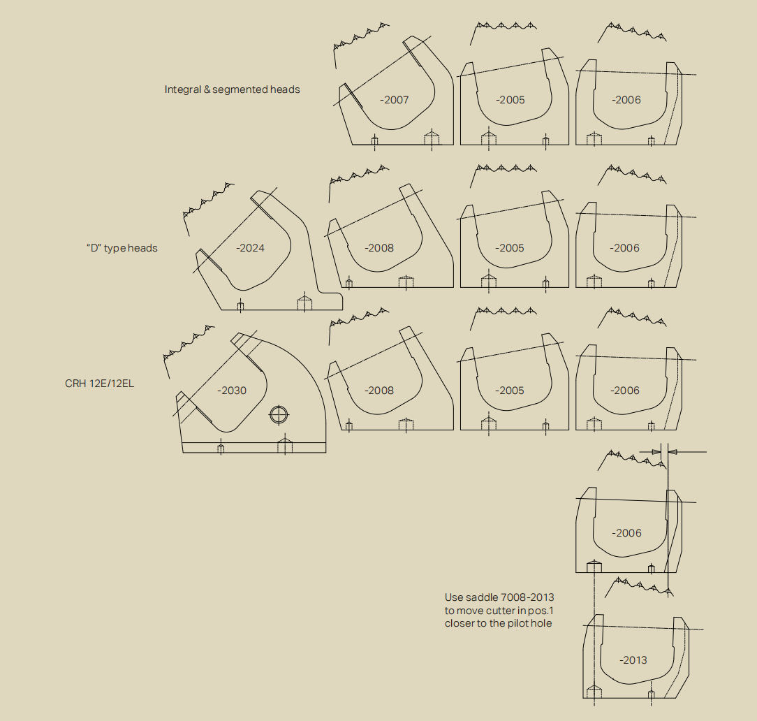
Different saddle types are required depending on the specific radial positioning and the overall type of the reaming head. The most frequent dressings fall under the part number series 7008-2XXX. The exact number and configuration of these types vary significantly with the reaming head diameter and design profile.
A major advancement for end-users is the implementation of a new, improved gauge saddle system on all "D" type reaming heads. Historically, reducing the overall diameter of a reamer required extensive modifications or replacing the entire head.
With the "D" type heads, operators can reduce the reamer diameter simply by changing the gauge saddles. This modular approach drasticaly reduces the inventory of heavy equipment a site needs to keep on hand and allows for rapid adaptation to changing shaft diameter requirements.
When utilizing the gauge saddle system, the geometry of the outermost cutting ring must remain perfectly symmetrical.Important: Make sure to use four gauge saddles of the exact same type (identical part numbers and markings) together on the reamer at all times. Mixing different gauge saddles will create an irregular outer profile, causing the reaming head to wobble, bore an uneven shaft, and potentially damage the pilot hole walls and the drill string.
Rock excavation in raise boring relies on "spalling"—fracturing the rock between the cutting tracks rather than grinding it all into dust. To achieve maximum spalling efficiency, the spacing between the innermost cutter (Position 1) and the pilot hole is hyper-critical.
This is where the special inner saddle, part number 7008-2013, comes into play. This specialized seat is designed to move the cutter in position 1 closer to the pilot hole when required. By optimizing this distance, the cutter exerts pressure that fractures the rock directly into the void of the pilot hole, significantly increasing the rate of penetration (ROP) and reducing cutter wear.
This special inner saddle is strictly required in Position 1 based on the relationship between the stem diameter and the reaming head stem fit. You must use the 7008-2013 saddle when:
A 9 7/8" stem is used in reaming heads with a 340 mm stem fit.
A 12 1/4" stem is used in reaming heads with a 360 mm stem fit (Note: The CRH10SE head is an exception to this rule).
A 13 3/4" stem is used in reaming heads with a 390 mm stem fit (Note: The CRH12E head is an exception to this rule).
Failure to use the 7008-2013 saddle under these specific configurations will result in excessive spacing between the pilot hole and the first cutter, leading to "rock coring" at the center, terrible spalling efficiency, and potential damage to the stem itself.
The mounting of saddles onto a raise boring reaming head is a highly engineered procedure that leaves no room for guesswork. By strictly observing position marks, sequencing the stem installation properly, adhering to the 1200 Nm torque specs with fresh bolts, and understanding the strategic use of gauge saddles and the 7008-2013 inner saddle, end-users can drastically improve the reliability and efficiency of their raise boring operations.
This website uses cookies to ensure you get the best experience on our website.




 Phone
Phone E-mail