
Abstract:For terminal users of Raise Boring Machines (RBM), the precise alignment and sequential mounting of cutter saddles are fundamental to operational success. Misalignment can lead to severe equipment damage, irregular boreholes, and excessive downtime. This article provides a deep dive into the spatial geometry of reaming heads, explaining how to accurately interpret position marks on the head frame and the crucial role of dowel pins in load distribution. Furthermore, it details the absolute necessity of integrating the drill stem before mounting position 1 and 2 inner saddles, ensuring equipment safety and operational efficiency during underground excavation.
Core Keywords:RBM saddle positioning, Reaming head stem mounting, Dowel pins in raise boring, Seat of Cutter alignment, Position 1 and 2 saddles, Raise boring drill string, Head frame position marks.
A raise boring reaming head is a marvel of industrial engineering, designed to cut through solid bedrock by applying immense upward thrust and rotational torque. To achieve a smooth, circular shaft, every cutter must track in a highly specific concentric path. The foundation of this path is the saddle—the seat of the cutter.
If a saddle is mounted even a fraction of a millimeter out of its intended geometric location, the corresponding cutter will deviate from its track. This deviation causes irregular rock spalling, increased vibration, and uneven wear across the entire reaming head. For the terminal user, understanding how to perfectly position these saddles is the first step in maximizing the lifespan of the equipment and minimizing operational costs.
To assist maintenance crews and operators, the manufacturer permanently stamps position indicators directly onto the steel of the reaming head frame. However, correctly interpreting these marks in the dim, dusty environment of an underground mine or civil construction site requires meticulous attention.
The positions for the saddles are visibly marked on the side of the head frame. Before beginning the mounting process, the contact surfaces must be wiped entirely clean of grease and rock dust so these stamps are clearly visible.
Because reaming heads are designed to accommodate multiple saddle configurations (dressings) depending on the desired shaft diameter and rock conditions, you will frequently encounter locations with two position marks.
The Rule: If there are two position marks, the upper one always refers to the position nearest the head center.
Why it Matters: Misinterpreting this rule can result in a saddle being mounted too far outward or inward, destroying the symmetrical Cutting profile of the reamer. Operators must train their crews to universally recognize the upper mark as the inner-most indicator.
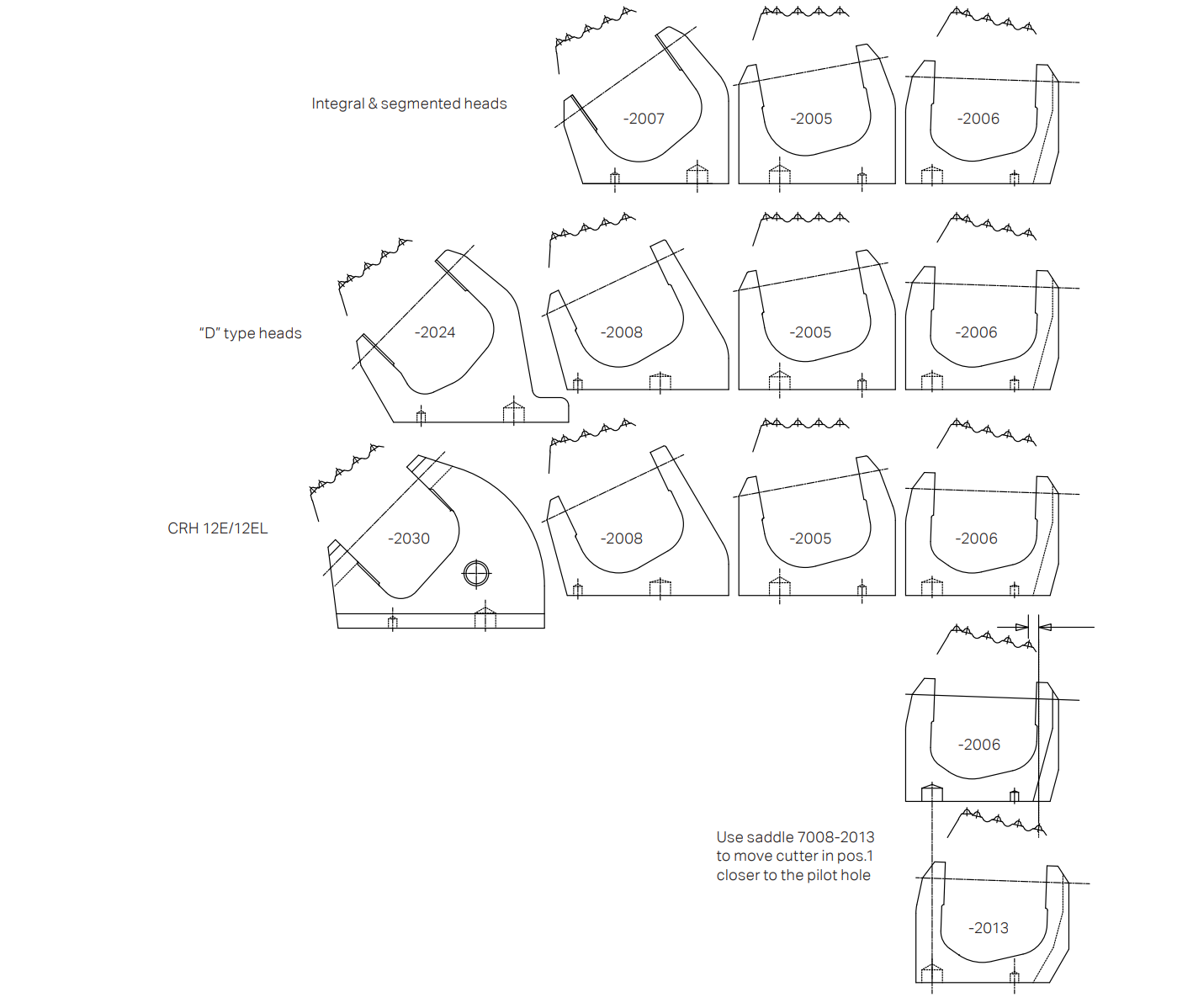
While bolts provide the clamping force necessary to hold the saddle against the head frame, they are not designed to align the saddle or bear the primary brunt of lateral shear forces. That responsibility falls to the dowel pins.
Dowel pins are precision-engineered solid steel cylinders that locate the saddles in their exact, correct position. When placing the saddle (seat of cutter) onto the frame, the dowel pins must slide smoothly into their corresponding machined holes.
As the reaming head rotates against the rock face, immense lateral (sideways) forces attempt to push the cutters out of alignment. The dowel pins act as a mechanical anchor, absorbing these shear forces and preventing the saddle from shifting. If a saddle is bolted down without properly seating the dowel pins, the shear forces will be transferred directly to the mounting bolts, which can rapidly lead to bolt fatigue, stretching, and catastrophic shearing mid-bore.
The most critical procedural error a maintenance crew can make involves the sequencing of the inner saddles (Positions 1 and 2) relative to the drill stem.
Note: Do not attach the saddles for position 1 and 2 before the stem is mounted.
Positions 1 and 2 are the innermost saddles, located immediately adjacent to the central bore of the reaming head where the drill stem must be inserted and secured. If these saddles are bolted into place first, their physical bulk will obstruct the stem mounting pathway.
The Risk: Forcing the heavy drill stem into the reaming head while the inner saddles are attached will almost certainly result in heavy steel-on-steel collisions. This can gouge the stem's sealing surfaces, damage the threaded connections, and shatter the hard-faced carbide buttons on the cutters.
The Solution: Always mount, align, and completely secure the drill stem to the reaming head frame first. Only after the stem is fully integrated and bolted should the crew proceed to mount the saddles for positions 1 and 2.
Mastering saddle positioning and stem integration is not merely a maintenance task; it is a critical operational safeguard. By strictly adhering to the upper-mark identification rule, relying on dowel pins for precise alignment and shear force absorption, and unfailingly mounting the stem before the inner saddles, terminal users can drastically reduce the risk of catastrophic equipment failure and maintain peak boring efficiency.
This website uses cookies to ensure you get the best experience on our website.




 Phone
Phone E-mail